|
|
|
|
 18-08-2006, 05:09 PM
|
#1 |
|
SiaoGu Gives You Wings
 Join Date: Jul 2001
Posts: 4,169
|
In this thread, I will share with you guys how to construct your own DIY wavebox. First of all, you will need to own the following components before starting this project.
You will need a controllable tunze turbelle stream pump either 6000, 6100 or 6200. The flowrate does not matter as 6000 is good enough for wavemaking. You will also need a 6080.50 magnet holder. This magnet holder will be able to support the wavebox up to 15mm glass thickness. Soldering stuff (not really necessary but good to have) Breadboard (For those that cant solder) First of all, I provide all these information FOC. Please do not use this information and try to sell it. Its meant to be shared FOC |

|

|
|
18-08-2006, 05:10 PM
|
#2 |
|
SiaoGu Gives You Wings
Join Date: Jul 2001
Posts: 4,169
|
You will need to construct a acrylic box with the dimension of 120mm X 140mm X H250mm. You can choose to use any color but I chose to use black.
You will need to drill a hole of 50mm, note that this is a very tight fit. If the hole is out of dimension, either your tunze will shake or you can't fit it in. 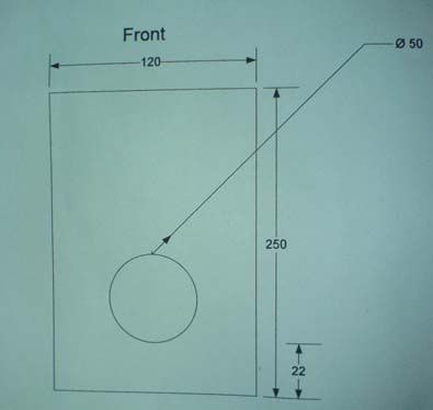
|
|
|
|
|
18-08-2006, 05:20 PM
|
#3 |
|
SiaoGu Gives You Wings
Join Date: Jul 2001
Posts: 4,169
|
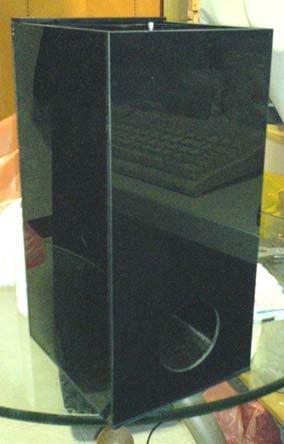
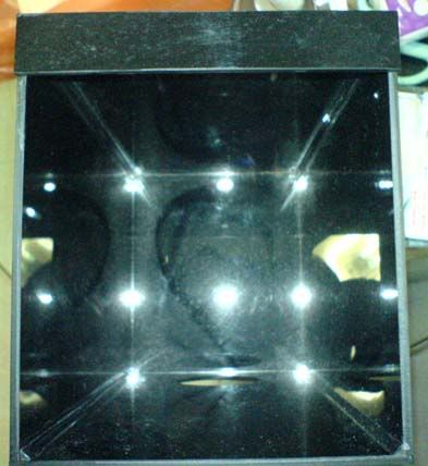
Here's the look of the acrylic box. Use the thinnest acrylic available, I'm using 3mm. This acrylic box will hold a tunze stream with a 6080.50 magnet at the back. You will need to insert the pump nozzle down first. Notice the top brace is added to prevent the magnet from sliding out of the box.
|
|
|
|
|
18-08-2006, 05:20 PM
|
#4 |
|
SiaoGu Gives You Wings
Join Date: Jul 2001
Posts: 4,169
|
Here's the breadboard. Basically its a test board with alot of holes for component testing. The breadboard is connected in 2 directions, I have drawn red lines over them to further enhance the understanding.
All the holes along the red lines are connected together. 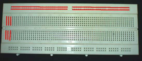
|
|
|
|
|
18-08-2006, 05:21 PM
|
#5 |
|
SiaoGu Gives You Wings
Join Date: Jul 2001
Posts: 4,169
|
This is the layout of the DIN 5 male socket which will be connected behind the blue box driver. Note that the pins are facing you.

|
|
|
|
|
18-08-2006, 05:21 PM
|
#6 |
|
SiaoGu Gives You Wings
Join Date: Jul 2001
Posts: 4,169
|
We are going to use the IC 555 which is a general purpose timer. This is the pin configuration of IC 555.
|
|
|
|
|
16-09-2009, 06:24 AM
|
#7 |
|
Guest
Posts: n/a
|
Hi Barracuda,
Great plans by the way. The only thing is, I'm confused on what parts I need. Could you kindly list out all the resisters, capacitors, etc... that you used for the controller? thank you. JV |
|
|
 |
| Currently Active Users Viewing This Thread: 1 (0 members and 1 guests) | |
| Thread Tools | |
| Display Modes | |
|
|


 Hybrid Mode
